Hand-Eye Calibration
This tutorial shows how to calibrate the rc_visard to the robot, in order to determine its position relative to the robot base frame, using Basler’s partner Roboception’s URCap. The hand eye calibration procedure is described in detail in the Hand Eye Calibration documentation.
Note
The calibration has to be performed every time the rc_visard is moved relative to the robot base.
Before we start
This tutorial assumes that the tutorials Getting started and Tuning of image parameters have been completed.
Externally mounted sensor - mounting the calibration grid
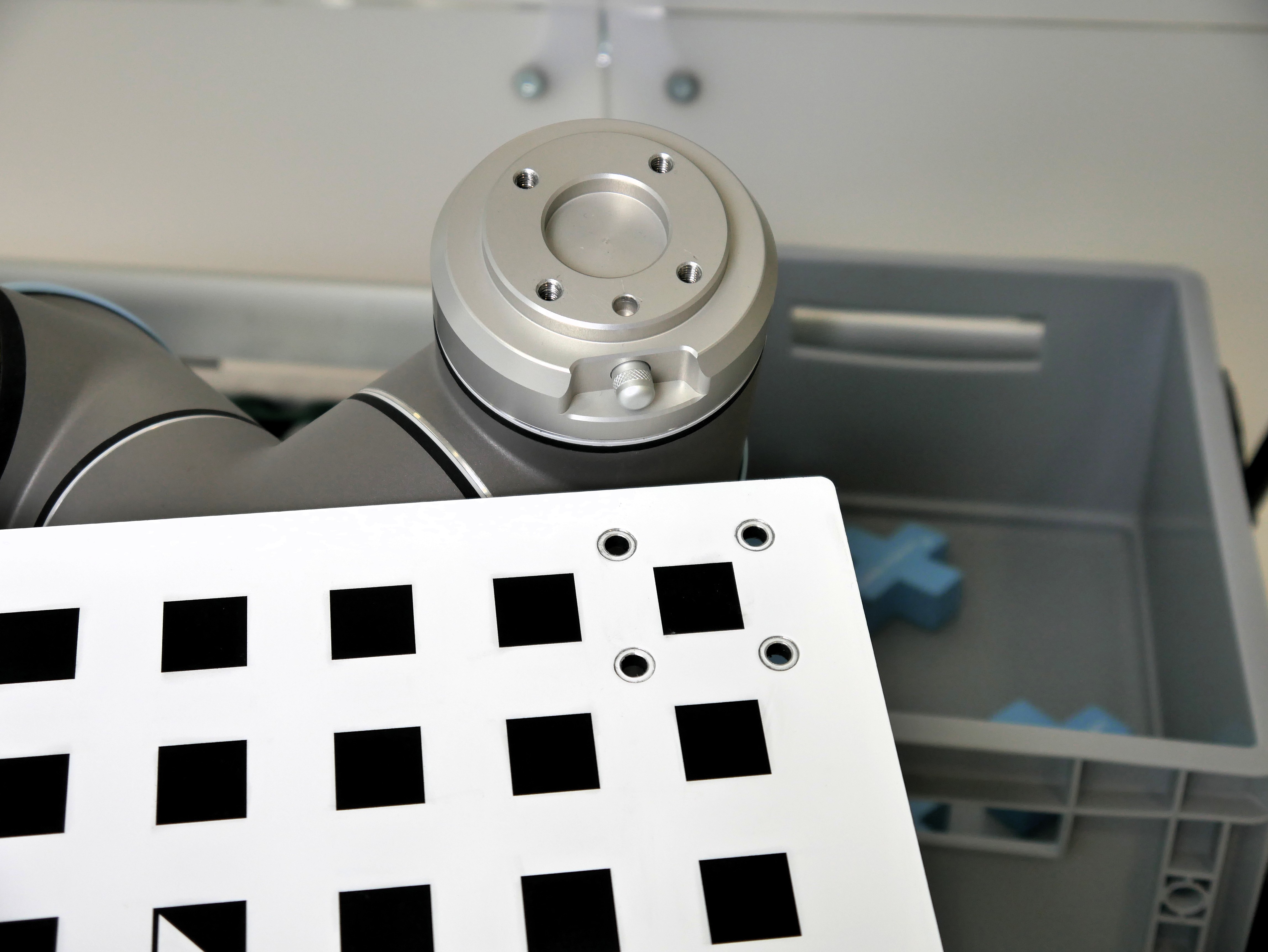
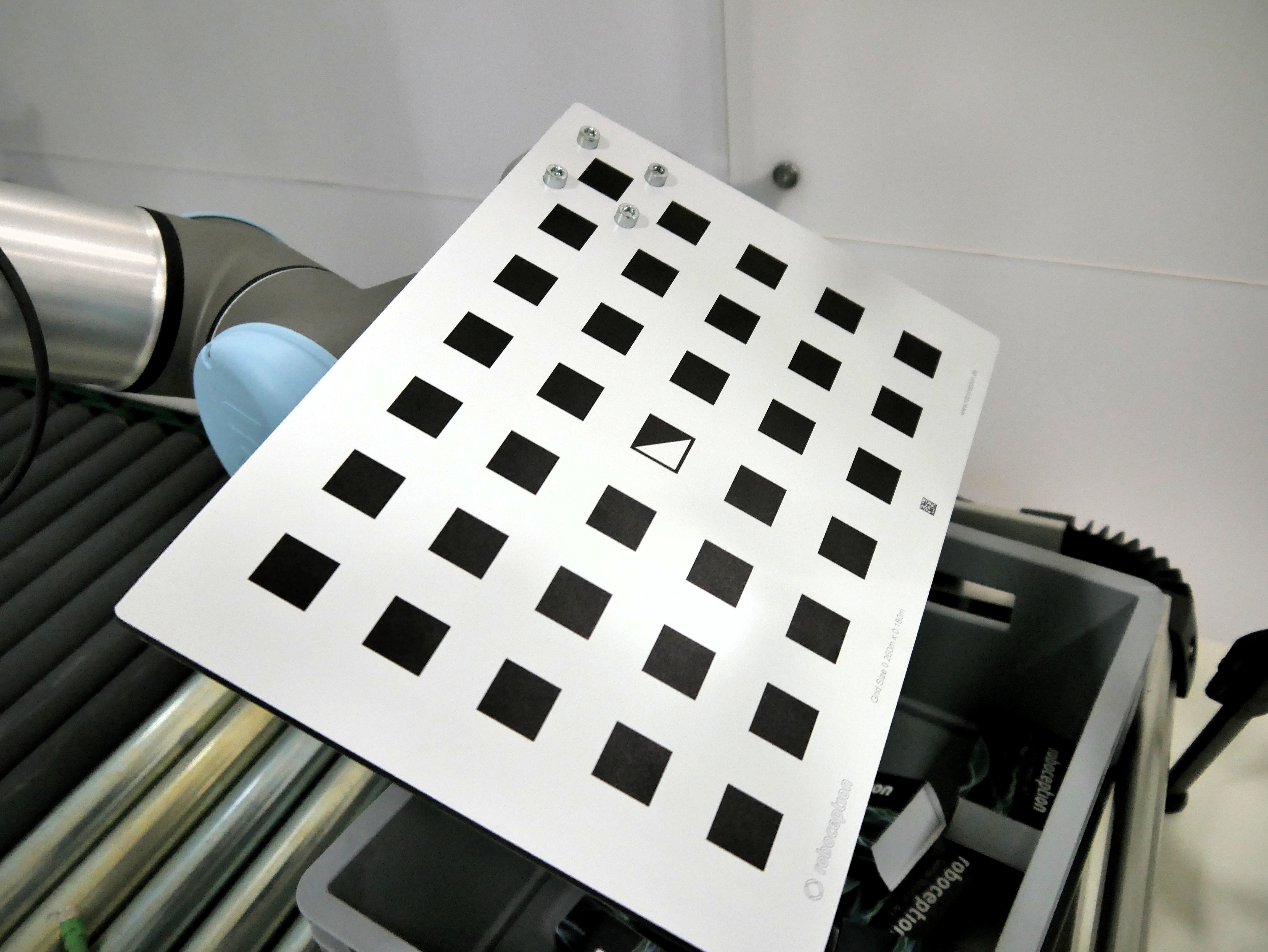
The calibration grid for Universal Robots is delivered with 4 holes in the lower left-hand corner and can be mounted directly to the flange of the robot with four M6 screws. The mounting point is not located in the center of the grid in order to reduce the chance of collisions with joint five during calibration movements. The grid should be mounted firmly with the positioning hole pointing towards the middle of the calibration grid in direction of the shorter side.
Sensor mounted on the robot - mounting the sensor
When using the sensor mounted on the robot, it has to be firmly mounted to the flange. Before starting the calibration, the weight of the TCP has to be updated in ‘TCP configuration’ and the calibration grid has to be placed in a way that it is not moving during the calibration.
Calibration program
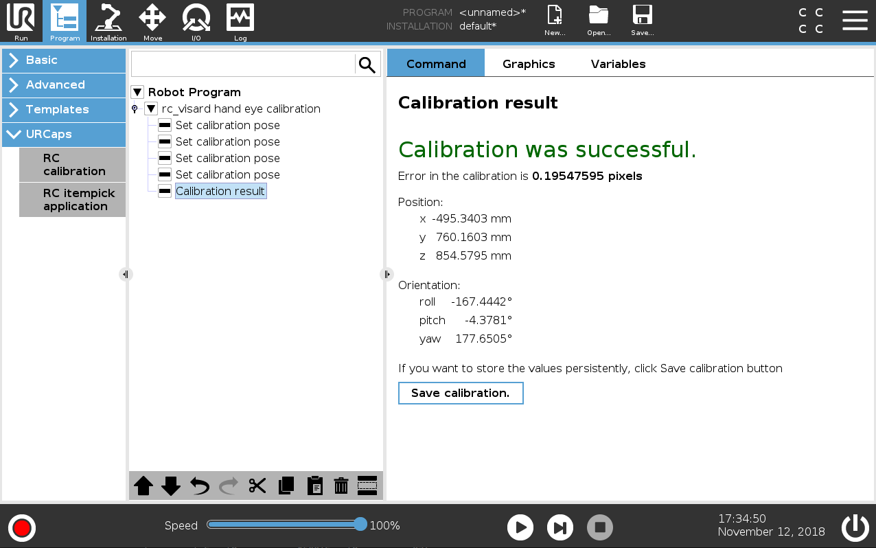
The rc_visard hand-eye calibration procedure is implemented as a program node. During the procedure the robot will move linear in tool-space with tool speed 0.5 m/s and tool acceleration 0.5 m/s2 between the poses taught by the user. The poses will automatically be sent to the rc_visard, and the calculated camera pose in the robot base frame will be shown in the ‘Calibration result’ node.
Note
The calibration result is not automatically stored on the rc_visard. It is the user’s responsibility to check the error associated with the calibration under ‘Calibration result’ and store it, provided the error is acceptable.
By default, for the duration of the calibration program with external camera, the TCP will be set to the middle of the flange, and the payload will be set to the payload of the mounted calibration grid. If the calibration grid is not mounted directly on the flange, or if it is not the only mounted element, TCP and payload have to be set accordingly in the installation node, and the checkbox ‘Use Basler TCP and payload’ in the main screen of calibration program has to be un-checked. For the calibration with robot mounted sensor, the user has to specify the payload in robot installation node prior to the calibration procedure.
In order to start a new calibration procedure:
- Create an empty program.
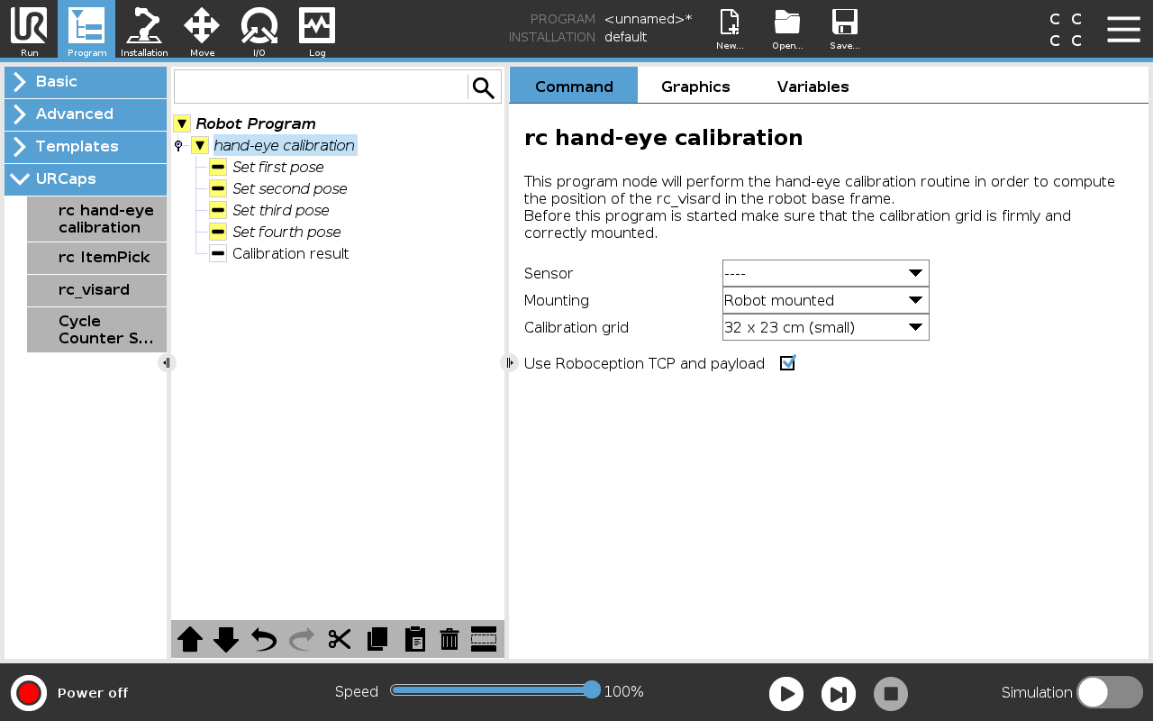
- Add the ‘RC calibration’ program node.
- Choose the sensor you want to calibrate and other calibration parameters (see Calibration parameters)
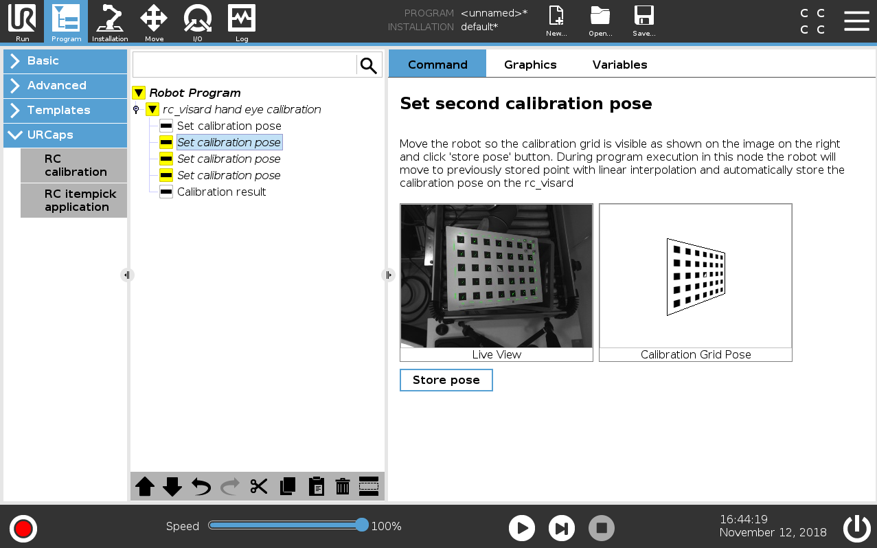
- Move the robot so that the grid is shown on the live view corresponding to the grid image on the right (see Set pose) and click the ‘Store pose’ button. Repeat this procedure for four poses.
- Run the program.
- When the popup informing about the success of the procedure is shown, go to the ‘Calibration result’ node, check the calibration result and click the ‘Store calibration’ button if the calibration should be stored persistently (see Calibration result).
