Basler Light Controller 4C-1.25A-84W-24V#
If you directly connect the lights to the controller, you can specify the output current supplied to the light which in turn controls the brightness. Alternatively, you can use a camera as an external trigger source allowing you to turn the light on or off.
Specifications#
General Specifications#
| Basler Light Controller 4C-1.25A-84W-24V | |
|---|---|
| Input Voltage | 100–240 VAC |
| Power Consumption | 120 W (typically) |
| Driver Method | Constant-current system |
| Brightness Control Method | Manual (10 mA – 1.25 A) or via current limit |
| Communication Port | 100/10 Mbps Ethernet (TCP/UDP IP) |
| Number of Channels | 4 |
| External Trigger Response | <50 µs |
| Protection | Short circuit protection Over temperature protection Current limit circuit |
| Channel 1–4 Output Voltage (Rate) | 8–24 VDC |
| Channel 1–4 Maximum Output Current (per Channel) | 1.25 A |
| 12 V Output Voltage (Rate) | 12 VDC |
| 12 V Maximum Output Current | 0.5 A |
| Max. Output Power | 30 W per channel; 84 W total (incl. channel 1–4 and 12 VDC Output) |
| Ripple Current | <15 % @ 24 VDC/1.25 A |
| External Trigger Input | 12–24 VDC; External On/Off trigger with High/Low active select |
| Size (L x W x H) | 147 x 100 x 129 mm |
| Weight | 1000 g (max.) |
| Connectors | 4 x 3-pin JST-SMR female connector (light) 7-pin PCB terminal block connector (trigger input) RJ45 Ethernet connector 3-pin C14 connector (power input) |
| Conformity | CE (includes RoHS), UKCA, FCC, KC, REACH, PSE |
| Package Contents | Basler Light Controller 4C-1.25A-84W-24V DIN rail bracket and screw (2200001191) 7-pin DC trigger connector (2200001264) |
| Accessories | AC power supply cable Basler Lights |
Mechanical Specifications#
Requirements#
Environmental Requirements#
Temperature and Humidity#
| Temperature during operation | 0–40 °C (32–104 °F) |
| Humidity during operation | 30–85 %, relative, non-condensing |
| Storage temperature | -20–60 °C (-28–140 °F) |
| Storage humidity | 20–85 %, relative, non-condensing |
Electrical Requirements#
Power must be supplied to the controller via the 3-pin C14 connector labeled AC INLET.
| Voltage Requirements | Power Consumption |
|---|---|
| 100–240 VAC | 120 W |
NOTICE – The controller produces high-energy pulses which may damage the controller if there is no protection against short circuits.
- Connect the outputs correctly.
Circuit Diagram for External Triggering#
Cable Requirements#
Power Supply Cable#
NOTICE – Using incorrect power supply cables may damage the controller.
Always use one of the following power supply cables:
- 100–120 VAC:
- SVT or SJT
- AWG18
- length: 3 m max.
- dielectric strength: 125 VAC min
- 200–240 VAC:
- H05VV-F
- AWG18
- length: 3 m max.
- dielectric strength: 250 VAC min
Controller-to-Light Cable#
The maximum cable length is 8 m.
For optimum performance and ease-of-use, Basler recommends using the following cables:
- BLC-BSL connect cable M8, 2m (order number: 2200001192)
- BLC-BSL connect cable M8, 5m (order number: 2200001193)
- BLC-BSL connect cable M8, 8m (order number: 2200001194)
External Trigger Cable#
The maximum cable length is 10 m.
Physical Interface#
| Part | Function | |
|---|---|---|
| 1 | Brightness / Function button | Used to configure the controller in manual mode |
| 2 | LEDs L1–L4 | Indicates the channels in use |
| 3 | Four 3-pin JST-SMR female connectors (channel 1–4) | Light connectors |
| 4 | Ethernet connector | Connects the controller with the computer |
| 5 | 3-pin C14 connector (AC IN 100-240V) | Power input |
| 6 | 7-pin PCB terminal block connector (TRIG) | Trigger input |
| 7 | Mode selector (MANU / ETHERNET) | Switches between manual and Ethernet mode |
| 8 | Reset button | Resets settings to the default values |
| 9 | Channel selector | Switches between channels |
| 10 | LEDs | Indicates controller operation (see LEDs for details) |
| 11 | Display | Used to configure the controller in manual mode |
LEDs#
The controller has the following LEDs:
| LED | Colors and Meaning |
|---|---|
| A/mA | Green: Current unit is set to A. Off: Current unit is set to mA. |
| H/L | Green: Trigger signal is high (1). Off: Trigger signal is low (0). |
| Lock | Green: Keys are locked (manual mode only) Off: Keys aren't locked. |
| L1 | Green: Channel 1 is configured / in use. Off: Channel 1 isn't configured / in use. |
| L2 | Green: Channel 2 is configured / in use. Off: Channel 1 isn't configured / in use. |
| L3 | Green: Channel 3 is configured / in use. Off: Channel 1 isn't configured / in use. |
| L4 | Green: Channel 4 is configured / in use. Off: Channel 1 isn't configured / in use. |
Connector Pinout#
3-Pin JST-SMR Female Connector#
| Pin | Function |
|---|---|
| 1 | Light + |
| 2 | Not connected |
| 3 | Light - |
7-Pin PCB Terminal Block Connector#
| Pin | Function |
|---|---|
| 1 | 12 VDC - |
| 2 | 12 VDC + |
| 3 | Common |
| 4 | Channel 4 |
| 5 | Channel 3 |
| 6 | Channel 2 |
| 7 | Channel 1 |
Ethernet Connector#
Precautions#
WARNING – Fire Hazard / Electric Shock Hazard
Unapproved disassembly or modification of the product may result in fire or electric shock.
- Do not disassemble or modify the product.
Exposure of the product to water may cause fire or electric shock or both.
- Make sure that the product is not exposed to water or any other liquids.
Connecting or disconnecting the light cable while the power supply is switched on may result in circuit damage, fire caused by small sparks, or electric shock.
- Connect or disconnect the light cable only after turning off the power supply.
Damaging the cables of the product may result in fire or electric shock or both.
- Before moving the product, disconnect all cables.
WARNING – Electric Shock Hazard
Connecting or disconnecting the controller and cables with wet hands may result in electric shock.
- Do not connect or disconnect components with wet hands.
Unapproved power supplies may cause electric shock. Serious injury or death may occur.
- You must use power supplies that meet the Safety Extra Low Voltage (SELV) and Limited Power Source (LPS) requirements.
WARNING – Fire Hazard
Continuing to use the product after detecting smoke, heat, smell, noise, etc. may cause fire or electric shock or both.
- Stop using the product immediately and turn off the power supply.
Using the wrong material to remove dust or other foreign substances from the electrodes may cause fire.
- To remove dust or other foreign substances, turn off the power supply and use only a dry cloth.
NOTICE – Improper handling may damage the product.
Improper handling may cause product failure.
- You must handle the product with care.
- Place the product on a firm, flat, and even surface.
- Do not drop the product or subject it to mechanical shock.
- Do not place the product in direct sunlight or high-humidity environment.
NOTICE – Product Failure
Incorrect handling of product cables may cause the product to malfunction.
- Do not bundle product cables with high voltage lines or power lines.
- Allow sufficient space when installing the cables.
- Do not bend cables beyond their natural bending radius or squeeze cables into a narrow space when wiring the product.
Short circuits will have an impact on the product and may cause product failure.
- Do not intentionally short-circuit the positive and negative output terminals.
- When installing the controller in your environment, don't insert the screws any deeper than 5 mm.
NOTICE – Incorrect voltage may damage the product.
Using the product outside of the safe range of input voltage may damage the product.
- Only supply the product with voltage within the safe range of input voltage.
NOTICE – Inappropriate cleaning substances may damage the product.
-
Using inappropriate cleaning substances may cause discoloration or deterioration of the product surface.
-
Don't wipe the product with organic solvents, e.g., paint thinner or benzene.
Installation#
NOTICE – Leaving the power source on while setting up the controller or connecting / disconnecting cables may result in malfunction of the controller.
Always turn the power source off when setting up the controller or connecting / disconnecting any cables.
NOTICE – Temperatures outside of the specified range may damage the controller.
You must provide sufficient heat dissipation. When installing the controller, leave sufficient space around the cooling vents on both sides to allow any heat to dissipate.
NOTICE – Electromagnetic interference (EMI) may negatively affect the quality of the controller.
Always connect the controller to functional ground.
Mounting the Controller On a DIN Rail#
To mount the controller on a DIN rail:
- Tilt the controller to hook over the DIN rail.
- Push down on the controller to fasten it to the DIN rail.
Connecting the Controller and the Light#
Connect the cables of the lights using the Light + and Light - pins of the 3-Pin JST-SMR female connector.
Connecting the Controller and the Camera#
To connect a camera as an external trigger source:
- Connect the open ends of the external trigger cable to the 7-pin PCB terminal block connector labeled TRIG.
- Tighten the locking screws (maximum torque 19 Ncm).
Connecting the Controller and the Power Supply Cable#
Plug the power supply cable into the controller's 3-pin C14 connector labeled AC INLET.
Connecting the Controller and the Host Computer#
If you want to operate the controller in Ethernet mode via web interface or Ethernet mode via Telnet protocol, plug an Ethernet cable connected with your host computer into the Ethernet connector of your controller.
Operation#
Your controller has three operation modes:
Operating the Controller Manually#
NOTICE – Currents outside of the specified output current range may damage the LEDs of the light.
You must supply the light with the correct output current, overdrive, and duty cycle as provided in the documentation of your light. If you don't adhere to these values in the configuration of your controller, the LEDs of your light may be damaged.
To operate the controller manually:
-
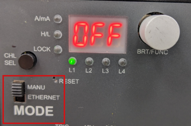
On the controller, switch the mode to MANU.
-
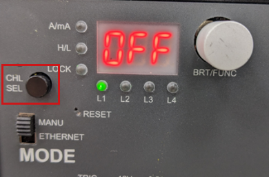
Press CHL SEL to select the channel you want to configure.
-
Configure how you want to operate the selected channel. You can configure the following modes for each channel:
-
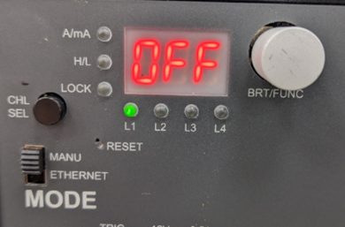
OFF mode: Turns off the light and disables the output of the selected channel.
-
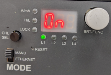
ON mode: Turns the light on permanently. In this mode you can only configure the brightness. The brightness can range from 0 mA to the current limit.
-
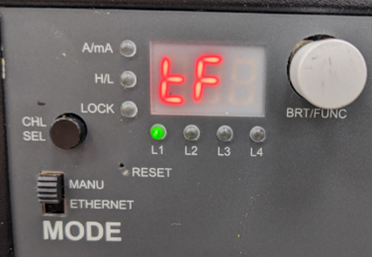
Trigger follow mode: In this mode, the light is controlled by a trigger signal, so you can use it as a strobe light. The brightness can range from 0 mA to the overdrive limit.
-
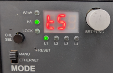
Trigger start mode: In this mode, the light is turned on by a trigger signal and stays on for a certain amount of time, so you can use it as a strobe light. The brightness can range from 0 mA to the overdrive limit.
-
To configure the light in these modes, use the BRT/FUNC button. You can rotate the BRT/FUNC button or press it.
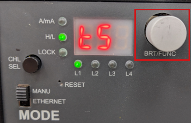
With the BRT/FUNC button, you can configure the following settings:
- OFF mode: Rotate clockwise → Next mode
- ON mode:
- Push → Adjust brightness → Push to save
- Rotate clockwise → Next mode
- Trigger Follow (TF) mode:
- Push → Adjust brightness → Push → Configure trigger signal → Push to save
- Rotate clockwise → Next mode
- Trigger Start (TS) mode: Push → Adjust brightness → Push → Configure trigger signal → Push → Configure strobe time → Push to save
Defining Current Limit and Overdrive#
The current limit defines the maximum current the controller may supply and therefore equals 100 % brightness. Check the documentation of your light to find out about its maximum allowed current.
The overdrive limit defines the maximum current the controller may supply in overdrive mode, which allows brightness levels above 100 %. Basler recommends using overdrive in strobe mode only, where you must also define the duty cycle. Check the documentation of your light to find out about its maximum allowed overdrive and duty cycle.
- Press the CHL_SEL and BRT buttons simultaneously.
- Press the BRT button again to change between current limit (
CL) and overdrive limit (OdL). - Rotate the BRT button clockwise or counterclockwise to increase or decrease the limit.
- Press the BRT button to confirm the setting and to exit the current limit setup.
The display shows the mode of the selected channel.

NOTICE – Currents outside of the specified output current range may damage the LEDs of the light.
You must supply the light with the correct output current, overdrive, and duty cycle as provided in the documentation of your light. If you don't adhere to these values in the configuration of your controller, the LEDs of your light might be damaged.
Adjusting the Brightness#
- Rotate the BRT button until the mode of your choice is displayed (ON, Trigger Start, or Trigger Follow). Then press the BRT button once.
- To increase the brightness, rotate the BRT button clockwise.
- To reduce the brightness, rotate the BRT button counterclockwise.
- Press the BRT button to confirm the setting.
By default, the brightness display shows the current in mA. If you rotate the BRT button so that the brightness exceeds 995 mA, the unit switches from mA to A.
Also, the step size changes from 5 mA per step to 10 mA per step, and the A/mA LED lights up:

Configuring the Trigger Signal#
In Trigger Start and Trigger Follow mode, you can define which signal transition activates the selected trigger (high or low). To do so:
- Select the Trigger Start or Trigger Follow mode.
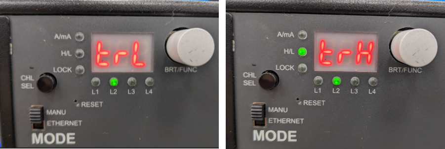
- Press the BRT button twice until you see
trH(Trigger High) ortrL(Trigger Low) on the display. - Rotate the BRT button to select the desired value (
trHortrL). - Press the BRT button to confirm the setting.
Configuring the Strobe Time#
In Trigger Start mode, you can configure the duration ("ON time") of the strobe light. To do so:
- Select the Trigger Start mode.
- Press the BRT button three times until the ON time is displayed.
- Rotate the BRT button clockwise or counterclockwise to increase or decrease the ON time.
To adjust the value more quickly, hold CHL_SEL while rotating the BRT button.
By default, the unit for the ON time is ms. Up until 10 ms, the step size is 0.01 ms per step. For values higher than 10 ms, the step size is 0.1 ms.

Locking the Keys#
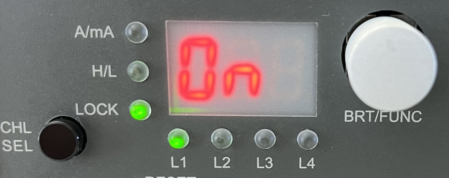
With this function, you can lock the keys of the controller. To lock or release the lock of the keys, press the BRT button for at least two seconds. The Lock LED lights green when the keys are locked.
Operating the Controller in Ethernet Mode via Web Interface#
To configure your controller via web interface:
- Connect the controller to a host computer using an Ethernet cable.
- Switch the mode selector to ETHERNET.
- Make sure your Ethernet port on the host computer is set to the same IP range and subnet mask as the controller:
- Default IP address:
192.168.1.2 - Default IP range:
192.168.1.1–192.168.1.255 - Default subnet mask:
255.255.255.0
- Default IP address:
-
Open a browser on the host computer and enter the following address:
192.168.1.2.
This is the default address for the web interface. The IP address is also displayed on the controller:
If the controller displays
000, the controller isn't connected to an existing Ethernet port: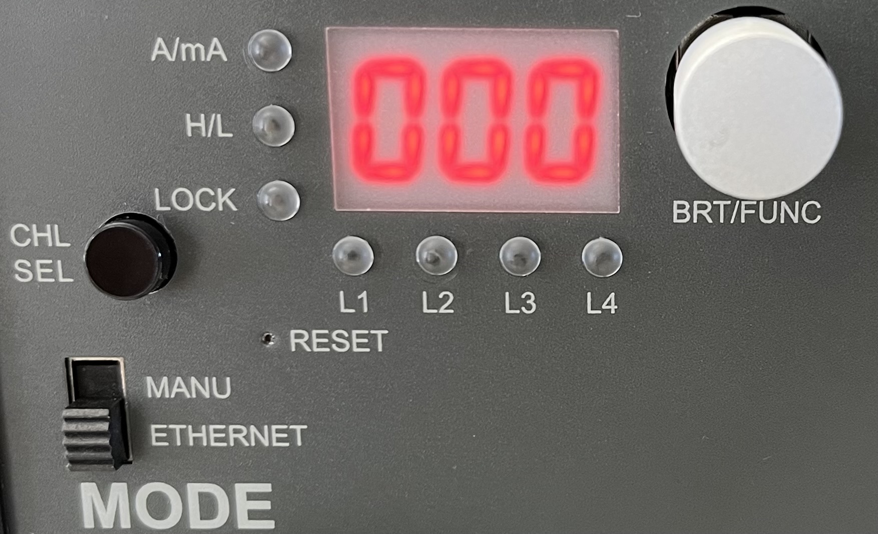
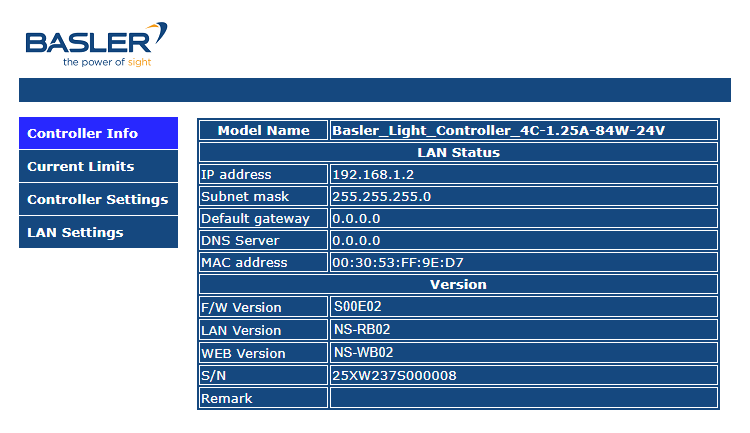
The web interface opens with the Controller Info page:
Configuring IP Address and LAN Settings#
On the Controller Info page, you can see all defined settings regarding LAN status and versions. To configure the LAN settings, open the LAN Settings page:
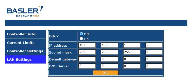
You can configure the following settings:
-
DHCP On: Choose this option if you're using a DHCP server in your network. The DHCP server automatically assigns IP addresses. To find out whether your computer is connected to a DHCP server:
- Open the Windows control panel.
- Select Network and Sharing Center.
- Click Ethernet.
The Ethernet Status dialog opens. -
Select Details.
The Network Connection Details dialog opens. If DHCP Enabled is set to Yes, then DHCP is enabled.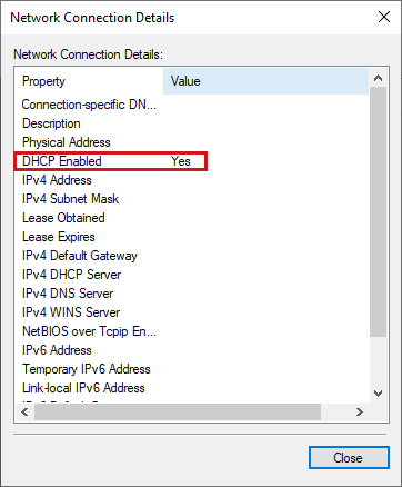
-
DHCP Off: Choose this option if you want to configure the IP address manually. Make sure that you use an IP address which isn't used by any other device in the same network. It's common to keep the first three numbers for all devices in the same network and change only the last number. For example, if a device in your network has the IP address
192.168.1.1, you can assign192.168.1.2as the controller's IP address.
Configuring Current Limit and Overdrive Settings#
In the web interface, open the Current Limits page.
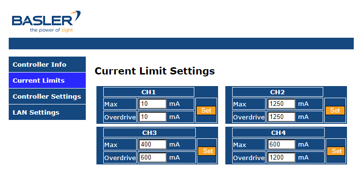
The current limit defines the maximum current the controller may supply and therefore equals 100 % brightness. Check the documentation of your light to find out about its maximum allowed current. Then, configure the maximum current limit in the Max field of the desired channel and click Set.
The overdrive limit defines the maximum current the controller may supply in overdrive mode, which allows brightness levels above 100 %.
To use overdrive in strobe mode, you must also define the duty cycle for the strobe mode, either in your trigger device or via the ON Time parameter on the Controller Settings page. Check the documentation of your light to find out about its maximum allowed overdrive and duty cycle. Then, configure the overdrive limit in the Overdrive field of the desired channel and click Set.
NOTICE – Currents outside of the specified output current range may damage the LEDs of the light.
You must supply the light with the correct output current, overdrive, and duty cycle as provided in the documentation of your light. If you don't adhere to these values in the configuration of your controller, the LEDs of your light may be damaged.
Configuring Your Lights#
In the web interface, open the Controller Settings page.
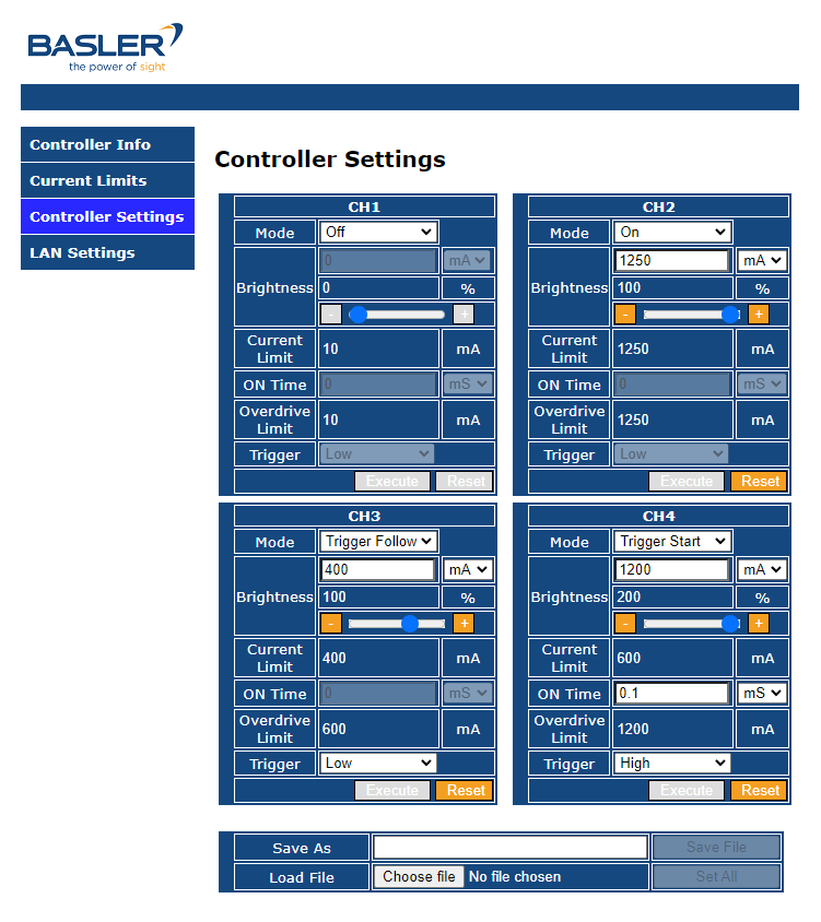
You can configure the following modes for each channel:
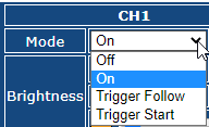
- OFF mode: Immediately turns off the light and disables the output of the selected channel.
- ON mode: Turns the light on permanently. In this mode you can only configure the brightness. The brightness can range from 0 mA (i.e. 0 %) to the current limit (i.e. 100 %).
- Trigger follow mode: In this mode, the light is controlled by a trigger signal, so you can use it as a strobe light. The brightness can range from 0 mA (i.e. 0 %) to the overdrive limit (i.e. 100 %).
- Trigger start mode: In this mode, the light is turned on by a trigger signal and stays on for a certain amount of time, so you can use it as a strobe light. The brightness can range from 0 mA (i.e. 0 %) to the overdrive limit (i.e. 100 %).
If you select Trigger Follow or Trigger Start, you can use the Trigger drop-down to define whether a high or low signal transition starts the trigger.
If you select Trigger Start, you can use the ON Time field to configure the duration of the strobe light (i.e., the active part of the duty cycle).
Click Execute to apply your changes. For safety reasons, the light is turned off, and it takes a few seconds before the Execute button is available again.
You can save your configuration to a .txt file via the Save File button.
You can load a configuration file and restore saved settings in the Load File pane:

After clicking Choose file, select the right file from your file system. The settings to be loaded for all channels will be shown on the Controller Settings page.
- If you click Set All, settings from the file will be applied and all previous settings will be overwritten.
- If you click Cancel, previous settings will be restored.
Operating the Controller in Ethernet Mode via Telnet Protocol#
You can also operate the controller via Ethernet using the Telnet protocol. To configure your controller via Telnet protocol, switch the mode to ETHERNET on the controller.
- Default IP address:
192.168.1.2 - HTTP port:
8080 - Telnet port:
23
You can use the following commands to configure your controller:
| No | Command | Action | Return (ASCII) | Function (x) | Values (y) |
|---|---|---|---|---|---|
| 1 | MODx:y | Set | CHx:My<CR><LF> | Sets the Mode of channel x (x = 1–4, y = 0–3) | 0: OFF 1: ON 2: Trigger Follow 3: Trigger Start |
| 2 | MODx? | Read | CHx:My<CR><LF> | Reads the Mode of channel x (x = 1–4) | |
| 3 | CHx:yyyy | Set | CHx:y<CR><LF> | Sets the brightness (current mA) of channel x (x = 1–4, yyyy = 10–1250) | < 1 A: 5 mA per step ≧ 1 A: 10 mA per step |
| 4 | CHx? | Read | CHx:y<CR><LF> | Reads the brightness of channel x (x = 1–4) | |
| 5 | STBSx:yyyy | Set | CHx:Cy<CR><LF> | Sets the Strobe time of channel x (x = 1–4, yyy = 0.1–100) | <10 ms: 0.01 ms per step ≧ 10 ms–100 ms: 0.1 ms per step |
| 6 | STBx? | Read | CHx:Cy<CR><LF> | Reads the Strobe setting of channel x (x = 1–4) | |
| 7 | TRGx:y | Set | CHx:Py<CR><LF> | Sets the Trig H/L of channel x (x = 1–4, y = 0 (low) or 1 (high)) | |
| 8 | TRGx? | Read | CHx:Py<CR><LF> | Reads the Trig H/L of channel x (x = 1–4) | |
| 9 | CLx:yyyy ILEDx:yyy | Set | CHx:Iy<CR><LF> | Sets the Output Current Limit of channel x (x = 1–4, yyyy = 10–1250) | < 1 A: 5 mA per step ≧ 1 A: 10 mA per step |
| 10 | CLx? ILEDx? | Read | CHx:Iy<CR><LF> | Reads the Output Current Limit of channel x (x = 1–4) | |
| 11 | OLDx:yyyy | Set | CHx:Oy<CR><LF> | Sets the Output Overdrive Current Limit (x = 1–4, yyyy = 10–1250) | < 1 A: 5 mA per step ≧ 1 A: 10 mA per step |
| 12 | OLDx? | Read | CHx:Oy<CR><LF> | Reads the Output Overdrive Current Limit of channel x (x = 1–4) | |
| 13 | STATUS? | Read | Exx<CR><LF> | Returns the status of the controller. 00: Normal 01/02/03/04: Channel 1/2/3/4 open 16: OTP 32: Power Error | |
| 14 | TEMP? | Read | yC<CR><LF> | Reads the controller temperature (y = xx.x) | °C |
| 15 | RESET | Set | Parameter Reset!<CR><LF> | Resets all parameters of the controller. The mode is set to OFF, other parameters are set to their minimum value. |
Resetting the Controller to Default Settings#
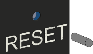
To reset all settings back to default, insert a ø 1.0 mm pin into the RESET hole. This also resets the IP address to the default value of 192.168.1.2.
