daA4200-30mci-MX8MM-VAR#
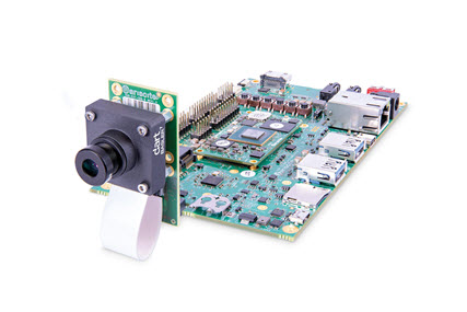
The kit contains a 13 MP dart camera module, a processing board based on the NXP i.MX8M Mini SoC, and accessories. With these components, you can build a test environment in which you can evaluate the camera module and plan how to integrate it into your embedded vision system.

Kit Contents#
The kit contains the following components:
- Basler dart daA4200-30mci camera module, S-mount
- Evetar lens M13B0618W F1.8 f6mm 1/3"
- DART-MX8M-MINI processing board
- microSD card with preinstalled system software
- Basler BCON for MIPI to VAR M / M Mini adapter board
- Flexible flat cable, 0.2 m
- USB 2.0 cable: A / Micro B, 1.8 m
- HDMI 2.0 cable: A / A, 1.5 m
- GigE cable: Cat 5e, 2.0 m
- Power supply: 5 V @ 4 A, AC adapter
- Mounting kit (includes camera mounting plate, spacer bolts, screws, and nuts)
Hardware Installation#
To install and connect the components provided in this kit:
- Remove the protective caps from the lens and mount the lens on the camera. Be careful not to damage any camera components by inserting the lens too deep.
-
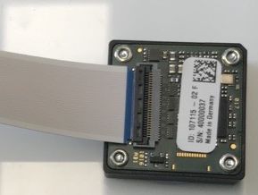
Connect the 0.2 m FFC cable to the camera. To do so:
- Open the black locking bar on the FFC connector.
- Push the end of the cable firmly into the FFC connector with the blue color facing away from the camera. See image below.
- Re-lock the connector by pushing the locking bar back into its original position.

-
Connect the other end of the 0.2 m FFC cable to the connector on the adapter board. Make sure that the blue part of the cable faces away from the adapter board.
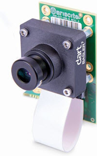
- Attach four spacer bolts to the front of the adapter board using four screws (M2x4) included in the mounting kit.
-
Attach the camera to the adapter board using four screws (M2x12). See image below.

-
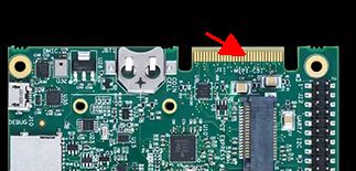
Connect the adapter with the mounted camera to the carrier board using the connector in the top right corner of the carrier board. See image below.

For more information about the processing board, download the VAR-DT8M CustomBoard Datasheet.
Acquiring Your First Images#
To acquire your first images using the pylon Viewer:
- Make sure that the following items are available:
- A Linux host computer.
- The following items delivered with this kit:
- USB 2.0 cable: A / Micro B, 1.8 m
- GigE cable: Cat 5e, 2.0 m
- microSD card
- Power supply: 5 V @ 4 A, AC adapter
- Make sure that the microSD card is inserted into the SD card slot of of the board.
- Configure the board to boot from SD card (see the Variscite Quick Start Guide).
- Connect the USB 2.0 cable to the board and to the host computer. This allows you to establish an SSH connection to the board.
- Open a shell on the host computer and start a terminal application, e.g., minicom. Configure the following settings for the terminal:
- Serial port configuration: 115200/8-N-1
- No hardware flow control
- No software flow control
- Connect the power supply to the barrel jack connector of the processing board.
- Connect the power supply to the mains socket.
The board boots up. - Connect the GigE cable to the board's Ethernet port and to the host computer.
- After the board has booted up, log in as root in a terminal application.
- Obtain the board's IP address, e.g., by entering
ip addr show. - Establish an SSH connection with X display forwarding:
ssh –X root@ip-address, whereip-addressis the board's IP address obtained in the previous step. - Start the pylon Viewer:
GENICAM_GENTL64_PATH=/opt/dart-bcon-mipi/lib /opt/pylon/bin/pylonviewer 2>/dev/null &
The pylon Viewer application lets you configure the camera, acquire and save images, and more. - Click the Continuous Shot icon to start image acquisition.
For more information about the Basler pylon Software Suite and on how to develop your vision applications using the SDK, visit the Basler pylon website.
Software Installation#
This Basler Embedded Vision Development Kit comes with a pre-loaded system image.
If you want to flash a new image onto the system, visit the following website: DART-MX8M-MINI Yocto Sumo.
If you want to build a new Yocto Linux system from scratch, visit the Variscite Wiki.