Network Configuration (blaze)#
The Linux-specific information in this topic is based on using the default desktop GUI of Ubuntu 20.04. Refer to the documentation of your Linux distribution for further details as there are multiple ways to configure the network interfaces under Linux.
Step-By-Step Guide to Network Configuration#
The following steps will guide you through the process of establishing blaze cameras in your network setup.
- Decide how you want to assign IP addresses to your cameras. Consider the following:
- How many cameras are you planning to use?
- How many network adapters are you using? Is there a dedicated adapter for every camera?
For more information, see Recommended Network Architectures. - Do you have a DHCP server available?
If you have a DHCP server, use it. This makes the configuration a lot easier.
If you don't have a DHCP server, your options are to use either static IP addresses or Auto IP:- Auto IP can only be used if you have no more than one network adapter configured to use Auto IP. Configuring multiple adapters for Auto IP makes camera discovery impossible.
- If you're using multiple network adapters with static addresses, each adapter must be in a different subnet.
- Configure the IP address of the network adapter(s).
- Configure the IP address of the camera(s) using the pylon IP Configurator.
-
Check the connection in the pylon IP Configurator.
- If the status is OK, everything is fine.
-
If the status is Not reachable, check the following:
- Make sure that the camera is not accessed by another application.
- Make sure that the adapter's subnet mask is the same as the camera's.
- Make sure that the addresses of the adapter and of the camera are in the same subnet.
Example: If the subnet mask is 255.255.0.0, the first two blocks of the IP addresses have be to the same. - Make sure that all other network adapters are configured for other subnets as the one that the camera is connected to.
- Make sure that no other network device has the same address as the camera.
-
If the camera is not listed, check the following:
- Is the camera physically connected to the correct network adapter?
- Disable the firewall for adapter that camera is connected to.
- Adjust performance settings.
- Troubleshooting
If there are dropped frames or error messages when streaming, the most likely cause is an unstable network connection or insufficient performance. - Check whether you can further optimize the network settings on your Windows or Linux system.
- Disable the firewall for the adapter that the camera is connected to.
Recommended Network Architectures#
There are two approaches to planning your network. The differences are listed below to help you choose a suitable setup.
Peer-to-Peer Network Architecture#
One option is to establish a direct peer-to-peer connection between your cameras and your host computer.
The cameras can be connected to individual GigE network adapters or to a multiport adapter in the host computer.
- Advantage: Each camera has an individual connection to the host computer. Thus, each camera has the full connection bandwidth available for transmitting acquired images. This means that you can operate each camera at its full acquisition rate.
- Disadvantage: The number of cameras that can be connected to a single computer is limited.
Info
In peer-to-peer connections, each adapter needs to be in a different subnet and each camera has to have an IP address in the subnet of the adapter that the camera is connected to.
Example: The IP addresses of the adapters are 192.168.1.1, 192.168.2.1, 192.168.3.1, etc. and the subnet masks are set to 255.255.255.0. The cameras can then have the following IP addresses: 192.168.1.100, 192.168.2.100, 192.169.3.100, etc. with the subnet masks set to 255.255.255.0.
Connecting via Network Switches#
As an alternative, you can establish a connection between your cameras and your host computer via network switches.
The example below shows a 1-port GigE network adapter connected to a 4-port network switch. You can also use multiport network adapters or multiple switches.
- Advantage: Allows you to connect many cameras to a single host computer.
- Advantage: Allows longer overall cable lengths because the cables between devices can each be up to 100 meters long.
- Disadvantage: The switch only has a single GigE connection to the computer. The cameras must share the bandwidth available on this single path. The bandwidth available on the single path is about 125 MByte/s.
Info
When multiple cameras are attached to a switch, the switch must have sufficient buffer capacity. This allows the switch to hold incoming data from the cameras while it transmits data on the single outgoing line.
All cameras have to have an address in the same subnet, i.e., the adapter's subnet.
Example: If the computer's address is 192.168.1.1, the cameras can take the IP addresses 192.168.1.100, 192.168.1.101, etc.
Recommended Network Adapters#
For best performance and reliability, Basler recommends using an adapter of the Intel PRO 1000, I210, I340, and I350 series.
Network Adapter IP Configuration#
These are the two most common ways to configure the IP addresses of network adapters:
- Assigning a fixed (also called "static" or "persistent") address
- Configuring automatic addressing via DHCP (Dynamic Host Configuration Protocol) or Auto IP (Automatic Private IP Addressing, based on link-local addresses (LLA)).
Windows#
Assigning a Fixed IP Address#
To assign a fixed IP address to a network adapter:
- Open the Network Connections window in the Windows Control Panel.
For quick access, press Win+R, typencpa.cpl, and press Enter. - Right-click the network adapter connection that is used with your camera and then click Properties.
The Properties window opens. - Double-click Internet Protocol Version 4 (TCP/IPv4).
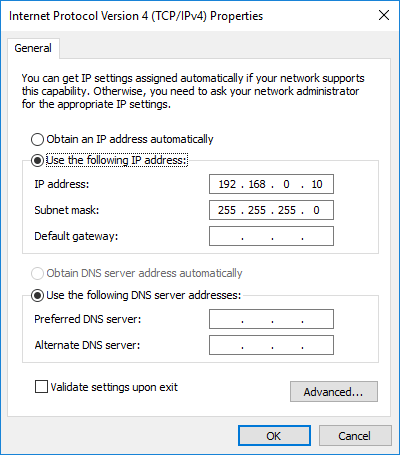
The Internet Protocol Version 4 (TCP/IPv4) Properties window opens. - Click Use the following IP address.
- In the IP address, Subnet mask, and Default gateway fields, type the IP address, subnet mask, and default gateway addresses.
-
In the Preferred DNS server and Alternate DNS server fields, type the primary and secondary DNS server addresses. (Normally, a domain name server is not needed.)
-
Repeat steps 2 to 6 for all applicable network adapters.
Info
During camera design-in, you can use the following settings to establish a network connection very quickly:
- Configure a fixed address for your network adapter in the automatic IP address range (169.254.0.1 to 169.254.255.254) with a subnet mask of 255.255.0.0.
- Configure Auto IP address assignment for your cameras.
- If your computer has multiple network adapters, each adapter must be in a different subnet.
- The recommended range for fixed IP addresses is from 172.16.0.1 to 172.32.255.254 with a subnet mask of 255.255.0.0 and from 192.168.0.1 to 192.168.255.254 with a subnet mask of 255.255.255.0. These address ranges have been reserved for private use according to IP standards.
- If you are assigning fixed IP addresses to your cameras, keep in mind that for a camera to communicate properly with a network adapter, it must be in the same subnet as the adapter to which it is attached.
Assigning an IP Address via DHCP / Auto IP#
If an adapter is configured to receive its IP address via DHCP / Auto IP, it operates as follows:
- The adapter tries to obtain an IP address from a DHCP server. If a DHCP server is available, it receives an IP address from the server and uses it.
- If no DHCP server is available, the adapter uses the Auto IP routine to assign itself an IP address.
The default setting for most network adapters is DHCP / Auto IP. In most cases, the adapter used with your cameras will not have a DHCP server available. So with the default settings, the adapter will end up using automatic IP addressing to assign itself an IP address.
Info
Only one adapter can be set to use Auto IP. If DHCP / Auto IP is configured on more than one adapter, the Auto IP assignment will not work correctly and the cameras will not be able to connect to the network via Auto IP.
If you have multiple network adapters in your computer, Basler recommends installing a DHCP server in your network or assigning static IP addresses to the adapters and to the cameras.
To assign an IP address using DHCP / Auto IP:
- Open the Network Connections window in the Windows Control Panel.
For quick access, press Win+R, typencpa.cpl, and press Enter. - Right-click the network adapter connection that is used with your camera and then click Properties.
The Properties window opens. - Double-click Internet Protocol Version 4 (TCP/IPv4).
The Internet Protocol Version 4 (TCP/IPv4) Properties window opens. - Make sure that Obtain an IP address automatically is selected.
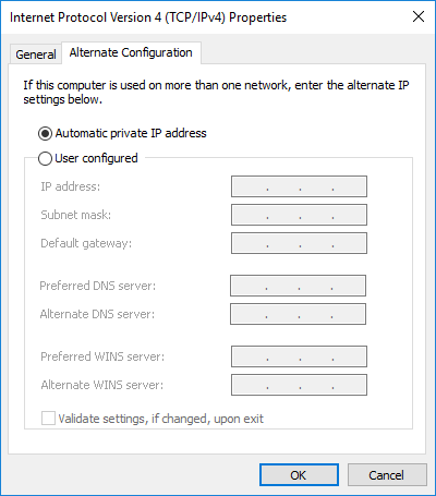
This makes the adapter check for a DHCP server as its first choice. - Click on the Alternate Configuration tab.
The settings on this tab are used to configure the Auto IP address assignment that the adapter will use if no DHCP server is found. -
Make sure that Automatic private IP address is selected.
Linux#
To configure the network adapter:
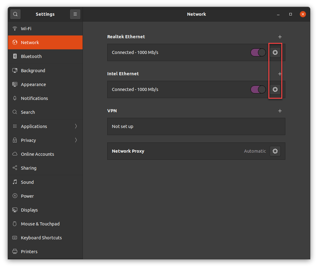
- Open the Settings app via Show Applications or the icon in the top right corner.
-
On the Network tab, click the gear icon next to the network adapter that your camera is connected to.
-
Click the IPv4 tab.
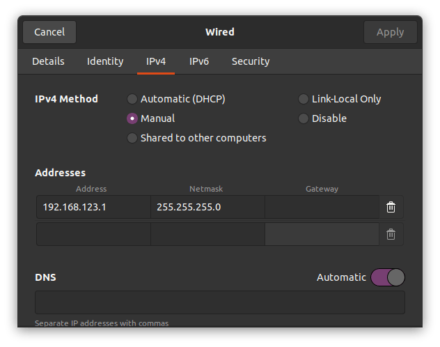
- For DHCP, set IPv4 Method to Automatic (DHCP).
- For static address assignment, set IPv4 Method to Manual and enter the Address, Netmask and, if required, Gateway in the Addresses area.
- For automatic address assignment, set IPv4 Method to Link-Local Only.
-
Click Apply to save the settings.
Camera IP Address Configuration#
To change the camera's IP configuration, use the pylon IP Configurator:
- Windows: Click Start > Basler > pylon IP Configurator.
- Linux: Issue the following command: /opt/pylon/bin/ipconfigurator
Info
For more information, see the pylon IP Configurator online help (Windows only) or the pylon IP Configurator section in this documentation.
Auto IP (LLA): This option is unavailable. However, if your camera is configured for IP address assignment via a DHCP server and no DHCP server is found, the camera falls back to Auto IP to configure itself with an IP address. Conversely, if you want to use Auto IP, select the DHCP option without providing a DHCP server.
Firewall Configuration#
Windows#
Disabling the Windows Firewall is an extreme measure that is not generally recommended. In some situations, however, it may be necessary in order to fix performance problems.
To turn off the firewall on selected network adapters:
- Press Win+R, type wf.msc, and press the Enter key.
The Windows Firewall with Advanced Security window opens. -
Click Windows Firewall Properties.
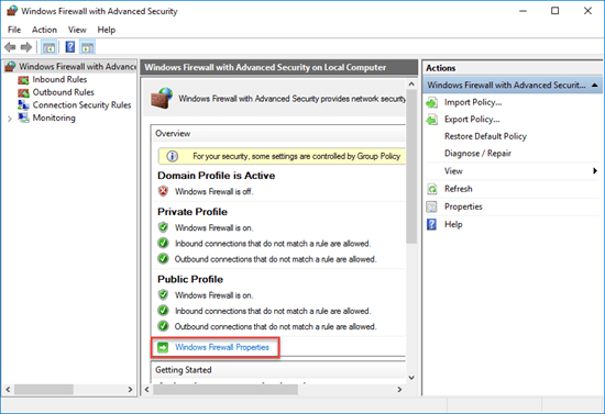
The Windows Firewall with Advanced Security on Local Computer Properties… window opens.
-
Click the tab of the profile where you want to turn off firewall protection.
Typically, this will be the Public Profile tab. However, if you're using a dedicated network card, Basler recommends also disabling firewall protection for the other profiles. -
Click Customize.
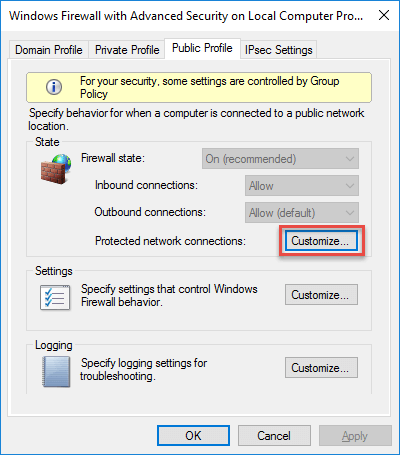
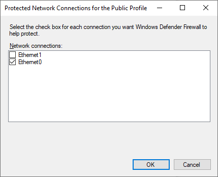
The Protected Network Connections for the Public Profile window opens. The window lists connections where the firewall is turned on.
-
Clear the connections where cameras are attached. This turns off their firewall protection.
- Repeat steps 3 to 5 for all profiles where you want to turn off firewall protection.
Linux#
The firewall must be disabled for network adapters to which cameras are connected. Otherwise, device discovery and receiving data streams from the camera may not work.
To disable the firewall, enter:
Performance Optimization#
Windows#
From a performance point of view, there are two relevant drivers available in the pylon Software Suite:
- GigE Vision filter driver
- Performance driver
To find out which driver has been installed:
- Open the pylon IP Configurator.
- Select your adapter.
Information about the adapter will be displayed in the bottom right area of the dialog. If it says Basler GigE Vision Adapter there, the performance driver is installed.
To adjust the settings, you can click the link in that area. It will take you directly to the Windows … Properties dialog.
Performance Driver#
If you're using the performance driver, optimization is not necessary. The driver chooses the optimum settings automatically.
GigE Vision Filter Driver#
If your network adapter doesn't support the performance driver, the filter driver will be installed by default. If that is the case, the network adapter must be configured before you can use it with your camera.
First, Basler recommends disabling certain protocols or services that may interfere with the filter driver.
To disable protocols or services:
- Open the Network Connections window in the Windows Control Panel.
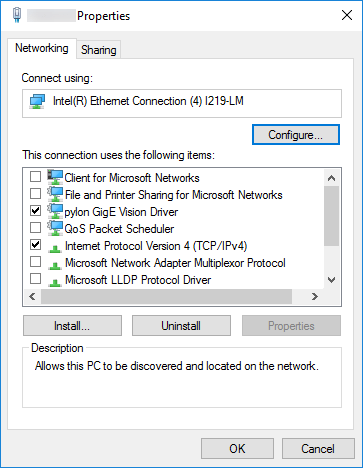
For quick access, press Win+R , typencpa.cpl, and press Enter. - Right-click the network adapter connection that is used with your camera and then click Properties.
The Properties window opens. -
Clear all check boxes except the pylon GigE Vision Driver and the Internet Protocol Version 4 (TCP/IPv4) check boxes:
-
Repeat steps 2 and 3 for all applicable network adapters.
Secondly, Basler recommends optimizing certain adapter properties.
To optimize the adapter properties:
- Open the Network Connections window in the Windows Control Panel.
For quick access, press Win+R , typencpa.cpl, and press Enter. - Right-click the network adapter connection that is used with your camera and then ckick Properties.
The Properties window opens. - Click Configure.
The configuration window of the network driver opens. - Click Advanced.
- Adjust the following properties (see note below):
- Select the parameter that relates to the number of receive descriptors (e.g., Receive Descriptors) and set it to its maximum value.
- Select the parameter that relates to the number of CPU interrupts (e.g., Interrupt Moderation Rate) and set it to a low value, e.g., 1000. The way to set the number of CPU interrupts may differ for your network adapter. You may have to use a separate parameter to enable the interrupt moderation.
- Select the parameter that relates to speed and duplex mode (e.g., Speed and Duplex Mode) and set it to automatic (e.g., Auto Negotiation).
- Repeat steps 2 to 5 for all applicable network adapters.
Linux#
The first thing to do to prevent packet losses is to increase the UDP receive buffer size. If you have done this and are still experiencing problems with dropped packets, try adjusting the real-time priority, ring buffer size, and the interrupt moderation rate.
Increasing the UDP Receive Buffer Size#
For stable image acquisition with blaze cameras, Basler recommends increasing the system's maximum UDP receive buffer size to ensure stable image acquisition. A maximum size of at least 4 MB is recommended.
To increase the maximum UDP receive buffer size, enter:
To make this setting persistent, you can add the net.core.rmem_max setting to the /etc/sysctl.conf file.
Setting the Real-Time Priority#
The pylon SDK uses a thread for receiving image data. It tries to set the thread priority of the receive thread to real-time thread priority to minimize jitter and packet loss. This usually requires special permissions.
However, for systems with a Linux kernel 2.6.13 or above, it is possible to allow processes without root privileges to set the real-time scheduling policy. On Ubuntu systems, you can control the maximum real-time priority for non-privileged processes on a per user or group basis via the /etc/security/limits.conf file.
For example, adding the following line to /etc/security/limits.conf allows all users to launch applications that will set thread priorities to real-time priority:
Changing /etc/security/limits.conf requires root privileges.
After changing the /etc/security/limits.conf file, you must log off and on again. For more details about the /etc/security/limits.conf file, see the limits.conf man page.
Basler recommends specifying a maximum real-time priority ≥1 for all users who will launch a pylon SDK-based application.
For kernel 2.6.12 or below, Basler recommends either starting pylon SDK-based applications with root privileges or setting the SUID bit of pylon-based applications.
Info
When the SUID bit of an application is set, the runtime linker ignores the value for the LD_LIBRARY_PATH variable when launching that application.
You can use the blaze Viewer to check if the GigE library has the required permissions for setting real-time thread priorities. After starting the blaze Viewer, open a camera device from the list of devices. In the Features pane, expand the Stream Parameters node. The ReceiveThreadPriority parameter indicates the thread priority of the receive thread. If the value is zero, the library didn't have the required permissions for setting real-time thread priorities. A value greater than zero indicates that the thread is scheduled with real-time thread priorities.
Increasing the Ring Buffer Size#
The receive (Rx) ring buffer defines the number of buffers used by the NIC driver to receive and process received image data from the camera. Usually, the ring buffer is set rather small and may need to be increased on systems that are receiving a high volume of network traffic.
To increase the ring buffer size using the ethtool command:
Example: To set the receive (Rx) and transmission (Tx) ring buffer size for the eth0 network interface to 4096, enter:
Info
The above configuration may not be supported by your network adapter. If ethtool returns an error, skip this optimization.
Configuring the Interrupt Moderation Rate#
The interrupt moderation rate (IMR) defines the trade-off between latency and performance. The IMR controls the interrupt throttle rate (ITR), the rate at which the controller moderates interrupts. The lower the ITR, the more responsive the driver will be, but also the higher the CPU load, because more interrupts will be generated. On the other hand, the higher the ITR, the higher the latency for processing interrupts, but the lower the CPU load. So, for most applications, Basler recommends using higher values for IMR, e.g., Extreme or 3600. If you need lower latency, use a lower value.
To configure the interrupt moderation rate using the ethtool command:
Example: To apply the recommended settings for the eth0 network interface, enter:
Info
The above configuration may not be supported by your network adapter. If ethtool returns an error, skip this optimization.
Troubleshooting#
Error when grabbing
Problem: When trying to grab images from multiple cameras, the error message "PrepareGrab (StartStreaming) failed for device" or "Insufficient system resources exist to complete the API" are displayed.
Solution: This condition can occur when the number of available open file descriptors is exhausted. The limit can often be increased for the current process with this command: ulimit -n
Camera not displayed
Problem: I can't see my camera in my application, even after waiting for more than one minute.
Depending on the camera's and adapter's IP configuration, it can take up to one minute until a valid IP address is assigned to the camera.
Solution: If the pylon IP Configurator is available, start the pylon IP Configurator (/opt/pylon/bin/ipconfigurator). Is the camera shown in the IP Configurator?
- If the camera's status is Not Reachable, check the camera's IP address and the adapter's IP address. Both the camera and the network adapter must use IP addresses within the same subnet. Refer to the Network Adapter IP Configuration section above.
- If the camera is not shown in the IP Configurator, the most likely reason is an enabled firewall. Disable the firewall for those network adapters that cameras will be connected to. If you don't have a firewall, enabled reverse-path filtering in the kernel may prevent detection of the camera. Refer to the next problem description for further details.
Can't configure camera
Problem: My application can't see my camera. I'm not able to reconfigure the camera to make it visible again.
Solution: First make sure you don't have a firewall enabled on the network adapter the camera is connected to.
If you still can't see the camera, reverse-path filtering in the kernel may prevent your application from detecting the camera. This can happen if the camera's IP address is not within the same subnet as the network adapter the camera is attached to.
To check whether filtering is turned on, run the following command:
In the output, look for the following lines:
Where eth1 is the network adapter the camera is connected to. The net.ipv4.conf.all.rp_filter is a global switch that must be turned off. The net.ipv4.conf.eth1.rp_filter shows whether filtering for the specified network adapter is enabled. To disable filtering, you must first turn off filtering for all and the specific network adapter (in this sample eth1). Use the following commands to change the filtering behavior at runtime:
Restart your application and check whether the camera(s) are detected. Reconfigure the camera(s) and use Write Configuration to make your changes persistent. You can re-enable filtering by executing the same commands but set a value of 1. If you want to turn off filtering permanently, you can edit the same values in /etc/sysctl.conf.
From Linux kernel version 2.6.32 onwards, the rp_filter settings allow strict and loose filtering. To accept asymmetrically routed packets, modify /etc/sysctl.conf:
Error code 0x81010014
Problem: Grabbing images leads to errors with error code 0x81010014. This error code indicates that the computer received incomplete images, i.e., network packets have been dropped.
Solution 1: Increase the maximum UDP receive buffer size to a value that is large enough. This allows the pylon SDK to increase the socket buffer size to 2 MB to ensure stable image acquisition.
Solution 2: Ensure that the application has the required permissions to set the receive thread's priority to real-time thread priority.
Solution 3: Check the cable. For GigE, Cat 5e cables are recommended. Poor cable quality or damaged cables can lead to unrecoverable transmission errors.
No images displayed
Problem: My application seems to acquire images but no images are displayed.
Solution 1: Start your application from the command line to see if it prints any messages.
Solution 2: Your application only receives incomplete frames. In that case, error messages such as Failed to grab image: GX status 0x81010014 are displayed. Refer to the previous problem for tips about how to solve this issue.
Solution 3: Grabbing images is failing for other reasons. Report the error messages printed by your application to Basler technical support.
Next Steps#
Your camera is now ready for use. For information how to get started, see Using blaze cameras.