Template Matching vTool#
It is best suited for detecting objects with blurry edges or borders that aren't clearly defined. Basler recommends using it for small objects as comparing the gray value information of pixels takes up a lot of processing time and memory.
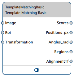
The Template Matching vTool accepts images via the Image input pin and outputs information about the matches found via its output pins.
It also outputs alignment transformation data that allows the Image Alignment vTool to align an input image with the reference image used during matching. This enables Measurements vTools to measure objects at different positions than the reference image.
If you use the ROI Creator vTool to specify a region of interest, the Template Matching vTool accepts the ROI data via its Roi input pin. In that case, objects are found only if the default reference point of the matching model lies within the region of interest.
A region of interest can be used to focus on objects in that specific region, to eliminate potential false candidates, or to reduce processing time.
The Regions output of the Template Matching vTool can also be used as Roi input for vTools with a Roi input pin. For more information, see the ROI Creator vTool topic.
You can use the transformation data supplied by the Calibration vTool to output the positions of the matches in world coordinates in meters (the Positions_m outpin pin becomes available). To do so, use the Calibration vTool before matching and connect the Transformation output/input pins of both vTools.

Template Matching Versions#
Two versions of the Template Matching vTool are available. The following table shows the differences between the versions. Click a version in the table heading to jump directly to the relevant section in this topic.
| Starter | Basic | |
|---|---|---|
| How do you define your template? | Fit a rectangle around the desired object. | Trace the contours of the desired object using the pen tools. |
| Can you specify a timeout? | No | Yes |
| Can you define a reference point? | No | Yes |
| Can objects at different angles from the object taught be detected? | Yes | Yes |
| Valid data types for Roi input pin | RectangleF | RectangleF, RectangleF Array, Region, Region Array |
How It Works#
By defining a template and applying it to your input image, you can gather the following information about the matches:
- Matching scores
- Positions
- Orientations
- Regions with visualizations of the matches
Template Definition#
The first step of template matching is the teaching of a model based on a representative image of the object to be detected by your application.
In this teaching image, mark the desired region and teach it. Your application uses this model to detect that object in your production environment.
Only objects that are completely visible in the image can be detected. That means the region marked in the template image must lie completely in the search image. Therefore, make sure to be very precise when marking the desired object and use the smallest pen possible.
Objects must be the exact same size and lie at the same distance to the camera as the object in the model taught.
Template matching is based directly on the gray value information of the model and the search image. Template matching uses a normalized cross-correlation algorithm.
Info
- Choose a representative image as a template.
- When marking the region of the desired object in the template image, choose regions that are characteristic for the object and that are generally present in the search images.
Using the Reference Point#
The Template Matching Basic vTool allows you to display a reference point in the object you've marked. By default, the reference point is placed at the center of gravity of your object. For most applications, this works well.
Info
If you're using a region of interest, the default reference point has to lie within the region of interest.
If required, however, you can move the reference point to a different position. An example would be a robotic picking application. In such a scenario, the vision system has to determine the gripping position for the robot taking into account the gripper of the robot and the shape of the objects to pick. Here, you could place the reference point accordingly to accomodate both these aspects.
To display the reference point, you must mark a template region in the teaching image first.
Model Settings#
To detect objects at different orientations from the object in the model taught, you can define a target angle and add a permissible tolerance value by which objects are allowed to deviate from the target angle.
Execution Settings#
- Matches: If the application is such that only a limited number of objects can occur, you may want to restrict the possible number of matches to exactly this number. This will increase processing speed and robustness.
- Score: A score value is calculated for every match. This score is the correlation coefficient between the region in the model and the region matched in the search image.
To find the optimum Score setting, start with a moderate value and run some test images. Observe the output values of the Scores pin. In order to securely find a match, always set the Score option to a value lower than the scores output by the Scores pin. This is best practice and recommended to allow for some tolerance.
Choose a score value between 50–80 % of the lowest score output values determined on the test image. In case the score is set too low, some unwanted matches may be detected as well. In that case, readjust the score value until only the intended objects are found in the test images. - Timeout: For time-critical applications, you can specify a timeout. A timeout helps in cases where the processing time varies or can't be foreseen, for example, if the image doesn't contain the object taught. By specifying a timeout, the detection process stops after the specified timeout and moves on to the next image.
Basler recommends setting the timeout a bit lower than the desired time limit. This is because the vTool doesn't stop the detection process immediately. Therefore, set the timeout to 70–80 % of the desired time limit.
Using Calibration#
The resulting positions of the matches can also be output in world coordinates in meters. To achieve this, connect the Transformation output pin of the Calibration vTool to the Template Matching vTool's Transformation input pin.
You must use the same calibration configuration for setting up the Template Matching vTool as for the actual processing.
Info
- The surface of the objects in the three-dimensional world space producing the two-dimensional images must lie, at least more or less, on the same plane in space. If this is the case, the effect of perspective distortion due to different positions of the object in the world and the edges in the image is negligible.
- Wide-angle lenses introduce significant perspective distortion due to the optical setup. For these lenses, the objects of inspection should be low in height relative to the object-to-camera distance. Alternatively, if the object height can't be neglected, choose a region in the template image at the same height level.
- Register the plane of the object by placing the calibration plate's surface in this plane during calibration setup.
Common Use Cases#
- Counting objects: In this case, only the number of elements at the Scores output pin is relevant.
- Locating objects in image coordinates: Use the Positions_px and Angles_rad output pins for subsequent processing.
- Locating objects in world coordinates: Use the Positions_m and Angles_rad output pins to transmit the positions of objects, e.g., to a robot to grasp the objects.
Template Matching Starter#
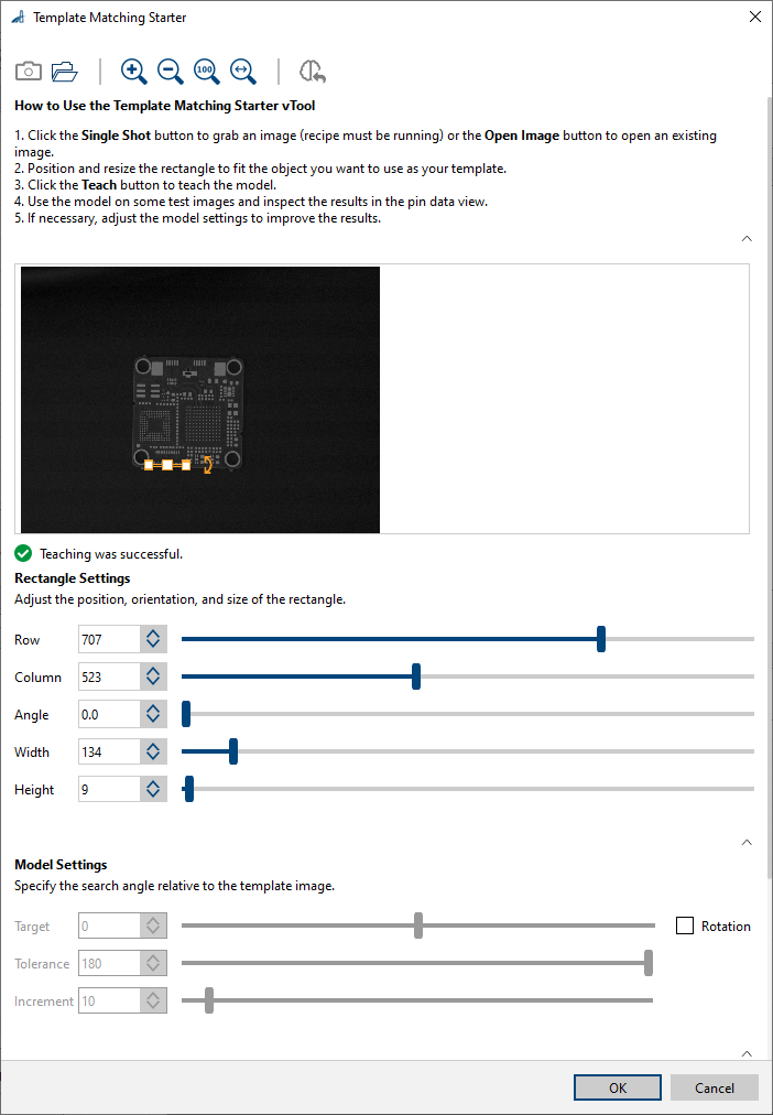
If you want to detect objects at different orientations, enable the Rotation check box. By doing so, the options in the Model Settings area become available. With these, you can define a target angle and a tolerance by which objects are allowed to deviate from the target angle. Using the Increment option, you can specify that detection takes place in steps. Choosing larger increments speeds up processing, i.e., makes detection faster.
You can specify how many objects you want to detect in an image or search for an unlimited number of objects. Limiting the number of matches to the expected number makes processing faster and more robust.
By adjusting the score value, you can specify how closely the objects have to match the object taught.
Template Matching Starter uses a bounding box for marking the region with the desired object. When you load an image, a rectangle is displayed automatically. Position this around the desired target object and resize it if necessary. You can use the handles of the rectangle for this or enter the desired values manually in the Rectangle Settings area.
Configuring the vTool#
To configure the Template Matching Starter vTool:

- In the Recipe Management pane in the vTool Settings area, click Open Settings or double-click the vTool.
The Template Matching Starter dialog opens. - Capture or open a teaching image.
You can either use the Single Shot button to grab a live image or click the Open Image button to open an existing image. - In the Rectangle Settings area, position and resize the rectangle to fit the object you want to use as your template.
- In the Model Settings area, specify whether you want to enable rotation.
This allows you to match objects at different orientations than your template. - Teach the matching model by clicking the Teach button on the toolbar.
- If desired, adjust the Matches setting in the Execution Settings area to limit the number of matches to a maximum.
- If necessary, adjust the Score setting so that only the target objects are found.
You can view the result of the template matching in a pin data view. Here, you can select which outputs to display.
Template Matching Basic#
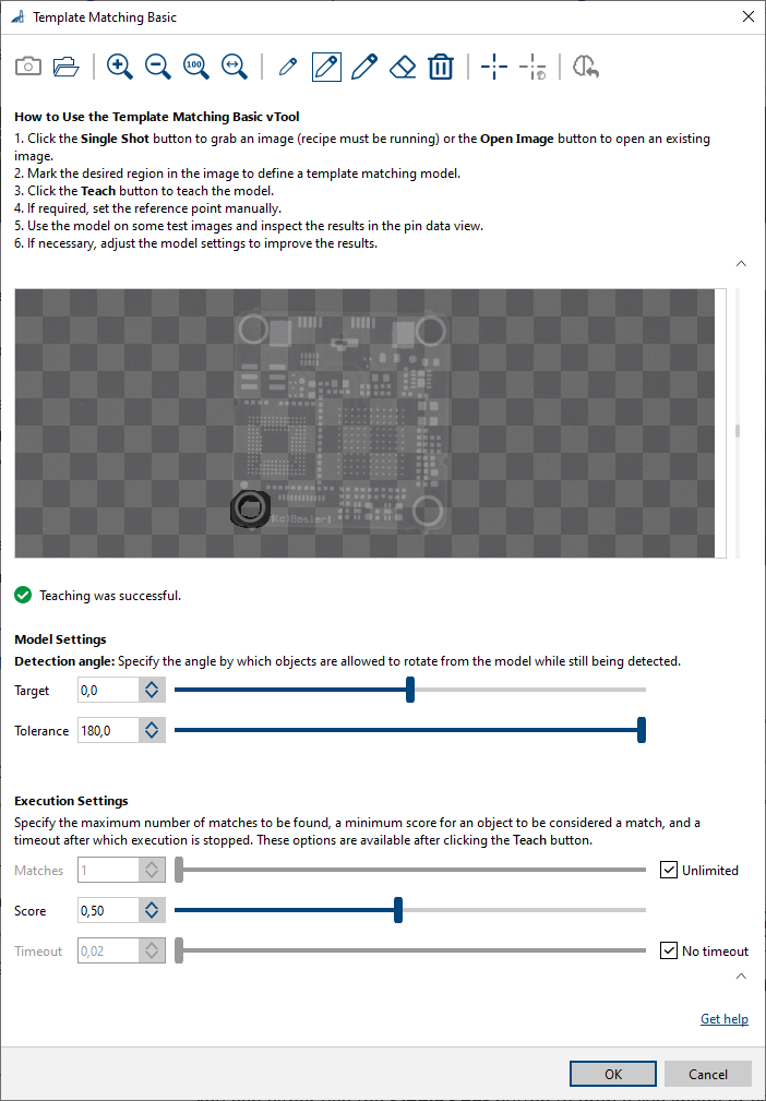
If you want to detect objects at different orientations, use the options in the Model Settings area. With these, you can define a target angle and a tolerance by which objects are allowed to deviate from the target angle.
You can specify how many objects you want to detect in an image or search for an unlimited number of objects. Limiting the number of matches to the expected number makes processing faster and more robust.
By adjusting the score value, you can specify how closely the objects have to match the object taught.
For time-critical applications, you can specify a timeout. A timeout helps in cases where the processing time varies or can't be foreseen, for example, if the image doesn't contain the object taught.
Configuring the vTool#
To configure the Template Matching Basic vTool:

- In the Recipe Management pane in the vTool Settings area, click Open Settings or double-click the vTool.
The Template Matching Basic dialog opens. - Capture or open a teaching image.
You can either use the Single Shot button to grab a live image or click the Open Image button to open an existing image. - Use the pens to mark the desired region in the image.
To correct the drawing, you can use the eraser or delete it completely. - Teach the matching model by clicking the Teach button on the toolbar.
- If required, display the reference point by clicking Show Reference Point.
The reference point is displayed at the center of the template region and the Set Reference Point Manually button becomes available. You can now drag the reference point to the desired position. If you click Set Reference Point Manually again, the reference point snaps back to its default position. - If desired, define a rotation angle and tolerance in the Model Settings area.
- If desired, adjust the Matches setting in the Execution Settings area to limit the number of matches to a maximum.
- If necessary, adjust the Score setting so that only the target objects are found.
- If you want to specify a timeout, clear the No timeout check box and enter the desired timeout in the input field.
You can view the result of the template matching in a pin data view. Here, you can select which outputs to display.
Inputs#
Image#
Accepts images directly from a Camera vTool or from a vTool that outputs images, e.g., the Image Format Converter vTool.
- Data type: Image
- Image format: 8-bit to 16-bit mono or color images. Color images are converted internally to mono images.
Roi#
Accepts a region of interest from the ROI Creator vTool or any other vTool that outputs regions or rectangles. Multiple rectangles or regions are merged internally to form a single region of interest. The Starter version accepts only RectangleF.
- Data type: RectangleF, RectangleF Array, Region, Region Array
Transformation#
Accepts transformation data from the Calibration vTool.
- Data type: Transformation Data
Outputs#
Scores#
Returns the scores of the matches.
- Data type: Float Array
Positions_px#
Returns the positions of the matches in image coordinates (row/column).
- Data type: PointF Array
Positions_m#
Returns the positions of the matches in world coordinates in meters (x/y).
- Data type: PointF Array
Angles_rad#
Returns the orientations of the matches in radian.
- Data type: Float Array
Regions#
Returns a region for every match found.
- Data type: Region Array
AlignmentTf#
Returns the transformation data that the Image Alignment vTool uses to align an object in the input image with the reference object used during matching.
- Data type: Transformation Data